Occurrence of combustion instabilities caused by the burner
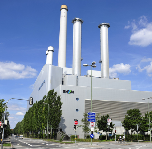
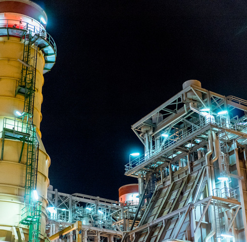
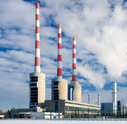
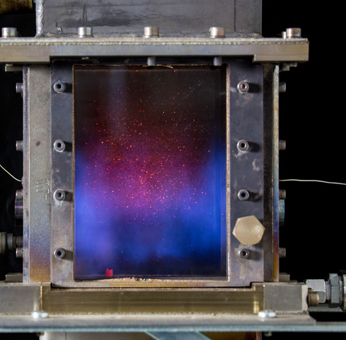
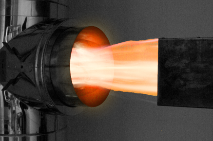
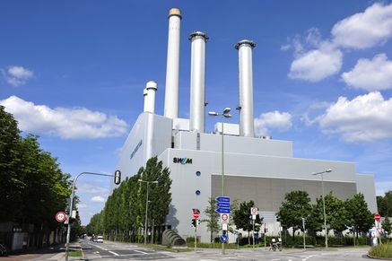
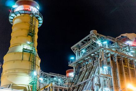
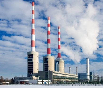
In comparison to small furnaces, i.e. condensing boilers, heating appliances, etc., which are intended primarily for domestic use and are offered as complete units, e.g. with burner, combustion chamber, heat exchanger and exhaust system, components from different manufacturers are individually combined in large furnaces. The products manufactured by the burner manufacturer are used, for example, with boilers from another manufacturer. Although combustion instabilities always depend on the overall system, i.e. burner, combustion chamber, exhaust gas and intake system, certain tendencies towards unstable behavior can be identified directly at the burner. For example, combustion phenomena based on fluid mechanical properties generate certain frequency components stronger than others. If these areas are close to an acoustic natural frequency of a boiler and other unfavorable conditions are also met, coupling between combustion and acoustics is probable, i.e. combustion instabilities are stimulated.
IFTA - a competent partner
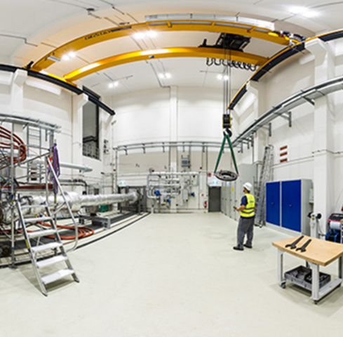
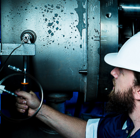
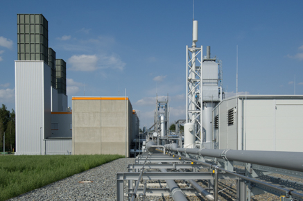
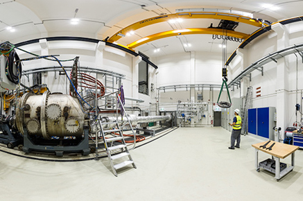
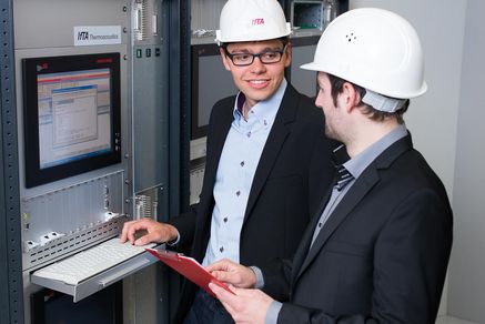
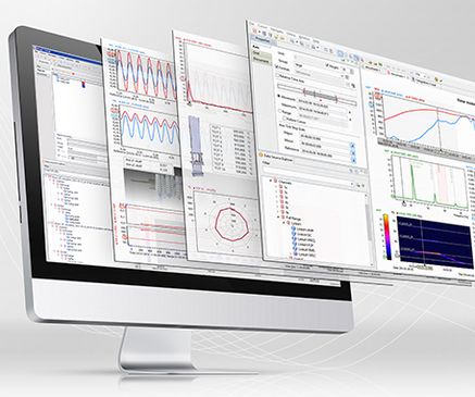
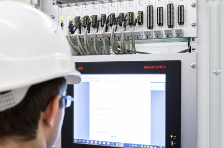
IFTA GmbH offers various investigations into the causes of combustion dynamics as described above. These investigations include measurements directly on the affected plant or on our customers' test benches. To support the experimental investigations of the phenomena, a numerical simulation of the acoustic behavior of the boiler geometries is also recommended. As a customer, you can rely on a competent, fast and cost-effective handling of your problems, as in the other areas. It goes without saying that we treat every issue confidentially.