IEPE Sup­ply with Gal­van­ic Iso­la­tion

IFTA GIA-IEPE: Ideal for IEPE Sen­sors

When mea­sure­ment sig­nals can­not be pro­cessed di­rect­ly by the data ac­qui­si­tion hard­ware, mea­sure­ment am­pli­fiers are re­quired to con­vert the sen­sor sig­nals. Here, gal­van­ic iso­la­tion be­tween the mea­sure­ment sig­nal and the ac­qui­si­tion hard­ware is cru­cial, as this pre­vents in­ter­fer­ence.

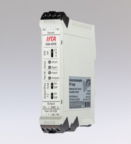
The IFTA GIA-IEPE (Gal­van­i­cal­ly Iso­lat­ed Am­pli­fi­er) is an iso­la­tion am­pli­fi­er with ad­justable IEPE input and gal­van­ic iso­la­tion.  For ev­ery­day use, this means high trans­mis­sion qual­i­ty of the sig­nal even over long dis­tances, safe­ty thanks to gal­van­ic iso­la­tion, and time sav­ings thanks to a lean mea­sure­ment chain that is less sus­cep­ti­ble to er­rors.

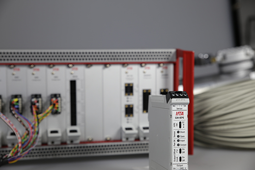
The IFTA GIA-IEPE is ideal for use with IEPE sen­sors as well as for retrofitting mea­sure­ment chains if the ex­ist­ing mea­sure­ment sys­tem does not offer IEPE feed­ing. IEPE is an in­dus­try stan­dard also known as ICP, CCLD, Isotron, Delta­tron, or Piezotron. The mod­ule can be com­bined with both sen­sors and charge am­pli­fiers that re­quire IEPE sup­ply. At the same time, the clean gal­van­ic iso­la­tion avoids dam­age and in­ter­fer­ence.

The GIA-IEPE Iso­la­tion Am­pli­fi­er as Part of the Mea­sure­ment Chain

The GIA-IEPE is ideal for IEPE sen­sors whose sig­nal is to be trans­mit­ted to a mea­sure­ment sys­tem with volt­age or cur­rent input.

The GIA-IEPE can also be used in com­bi­na­tion with a charge am­pli­fi­er that re­quires an IEPE sup­ply, e.g. the IFTA ChargeAm­pli­fi­er for high tem­per­a­ture sen­sors.

Bridg­ing large dis­tances:

  • Up to 100 m IEPE sup­ply (from sen­sor resp. charge am­pli­fi­er to GIA-IEPE input).
  • Up to 1000 m with cur­rent as out­put sig­nal (from the GIA-IEPE out­put to mea­sure­ment sys­tem).

Ad­van­tages of the Iso­la­tion Am­pli­fi­er IFTA GIA-IEPE

Flex­i­ble Sup­ply

The GIA-IEPE can be fed with 7 to 36 VDC volt­age. In ad­di­tion, the IEPE sup­ply can be ad­just­ed to match the sen­sor. This makes the mea­sure­ment am­pli­fi­er uni­ver­sal­ly ap­pli­ca­ble.

Über­brück­ung großer Dis­tanzen

Dank der starken IEPE-Ver­sorgung er­möglicht der GIA-IEPE eine Ka­bel­länge bis zu 100 m auf Seite der IEPE-Speisung sowie bis zu 1000 m auf Seite des Span­nungsaus­gangs.

In­te­grat­ed Error De­tec­tion

Short cir­cuit and cable break on the input side are au­to­mat­i­cal­ly de­tect­ed and re­port­ed by a de­fined out­put sig­nal and sta­tus LEDs.

Volt­age and Cur­rent Out­put

The GIA-IEPE in­te­grates a volt­age and cur­rent out­put. A DC off­set can be ac­ti­vat­ed on the volt­age and cur­rent out­puts in order to in­form the mea­sure­ment sys­tem that the mea­sure­ment chain is in op­er­a­tion. Without off­set, it is not pos­si­ble to dis­tin­guish whether the mea­sure­ment chain is faulty or whether there is ac­tu­al­ly no input sig­nal.

Gal­van­ic Iso­la­tion

The GIA-IEPE am­pli­fi­er is gal­van­i­cal­ly iso­lat­ed be­tween its input and out­put cir­cuits, in­clud­ing the as­so­ci­at­ed power sup­plies. This en­sures that there is no con­duc­tive path be­tween the input and out­put sec­tions, which in turn means safe­ty for op­er­a­tors and equip­ment.

Ad­justable Am­pli­fi­ca­tion

Due to the mod­u­lar am­pli­fi­er con­cept, in­di­vid­u­al ad­just­ments can be made cost-ef­fi­cient­ly.


IEPE-Sup­ply with Gal­van­ic Iso­la­tion GIA-IEPE

  • Overview
  • Tech­ni­cal Data
  • Op­tions
  • Ap­pli­ca­tion Ex­am­ples
Foto GIA Trennverstärker

High­lights

  1. Gal­van­ic iso­la­tion be­tween input and out­put side and to the sup­ply re­gion
  2. Ad­justable IEPE sup­ply
  3. Volt­age and cur­rent out­put
  4. In­te­grat­ed de­tec­tion of whether the input is short-cir­cuit­ed or open: Sig­nals er­rors at the volt­age and cur­rent out­put, if nec­es­sary, as well as op­ti­cal­ly via sta­tus LEDs
  5. An ad­di­tion­al DC off­set can be ac­ti­vat­ed at the volt­age and cur­rent out­put to com­mu­ni­cate to the mea­sure­ment sys­tem that the mea­sure­ment chain is in op­er­a­tion.
  6. Ex­cel­lent EMC char­ac­ter­is­tics
  7. Suitable for long cable lengths of up to sev­er­al hun­dred me­ters
  8. Ideal for use with IEPE sen­sors and IEPE charge am­pli­fiers
  9. Com­pat­i­ble with stan­dard mea­sure­ment tech­nol­o­gy
Foto GIA Trennverstärker

gen­er­al

Power sup­ply:7 ... 36 V
Hous­ing form:Head moount­ing
Con­nec­tions:Plug-in screw con­nec­tors
Gal­van­ic iso­la­tion:±250 VDC

IEPE Source

IEPE cur­rent:4 mA, 8 mA oder 12 mA
Error de­tec­tion:Short cir­cuit and open-cir­cuit de­tec­tion
Max. out­put volt­age:+26 Volt

Volt­age input

input range:±5 V AC cou­pling
High pass fil­ter:-3 dB at 0.2 Hz, 3rd order
Low pass fil­ter:-1 dB at 20 kHz

Volt­age out­put

Out­put volt­age:±5 V
DC off­set:0 V or 7 V
Max. out­put volt­age:+26 V
Error mes­sage:-6 V DC Off­set
Min­i­mum load re­sis­tance:2 kΩ

Cur­rent out­put

Out­put cur­rent:±5 mA
DC off­set:0 mA or 7 mA
Max. out­put volt­age:+12 V
Error mes­sage:-6 mA DC Off­set
Max. load:1 kΩ
Foto GIA Trennverstärker

Ad­just­ment of the am­pli­fi­ca­tion

Op­tion­al­ly, the am­pli­fi­ca­tion can be ad­just­ed ac­cord­ing to cus­tomer re­quire­ments.

Foto GIA Trennverstärker

Retrofitting of mea­sure­ment chains

The IFTA GIA-IEPE is ideal if mea­sure­ment chains are retro­fit­ted and the ex­ist­ing mea­sure­ment sys­tem does not pro­vide IEPE sup­ply. It can be com­bined with both sen­sors and charge am­pli­fiers that re­quire an IEPE sup­ply, while at the same time en­sur­ing that clean gal­van­ic iso­la­tion pre­vents dam­age and in­ter­fer­ence.

Ex­change of mea­sure­ment chains

If ex­ist­ing mea­sure­ment chains are to be re­placed, the IFTA GIA-IEPE proves to be a valu­able op­tion: thanks to its ad­van­tages such as IEPE sup­ply, gal­van­ic iso­la­tion and in­te­grat­ed error de­tec­tion, it en­ables the max­i­mum flex­i­bil­i­ty with the high­est re­li­a­bil­i­ty and sig­nal qual­i­ty.

Foto GIA Trennverstärker

Test­ing

  • Im Siemens Clean En­er­gy Cen­ter, Ber­lin führt die AD4Pro zu maßge­blich­er Kom­plex­ität­sre­duzierung bei der Mess­kette und vere­in­facht so den schnellen und fehler­freien Kon­fig­u­ra­tionswech­sel

Ser­vice

  • Ser­vi­cein­ge­nieure wer­den mit täglich wech­sel­nden Mes­sauf­gaben kon­fron­tiert. Mit der AD4Pro sind sie auf alle Sen­sortypen vor­bere­it­et ohne zusät­zliche ex­terne Ver­stärk­er mitzunehmen

Forschung

  • Bei Ladungsver­stärk­ern sind in­te­gri­erte Oper­a­tionsver­stärk­er mit di­rekt an­schließen­der A/D Wand­lung In Sachen Sig­nalqual­ität un­schlag­bar. Der Lehrstuhl für Tur­bo­maschi­nen und Flu­gantriebe der TU München setzt daher für seine Hochtem­per­atur-Piezo-Druck­aufnehmer auf die AD4Pro.

Suitable for Use in High Volt­age Ap­pli­ca­tions

Gal­van­ic iso­la­tion - a key De­sign Fea­ture of IFTA Prod­ucts

Gal­van­ic iso­la­tion is a key de­sign fea­ture of our prod­ucts that makes them par­tic­u­lar­ly suit­able when var­i­ous un­de­fined or very dif­fer­ent ground po­ten­tials are present, for ex­am­ple, in high-volt­age and mul­ti­sen­sor ap­pli­ca­tions. Our lat­est ex­am­ple is the GIA-IEPE iso­la­tion am­pli­fi­er with ad­justable IEPE sup­ply and gal­van­ic iso­la­tion.  It may be used to pro­tect ex­pen­sive mea­sure­ment equip­ment from dam­age due to over­volt­age in high-volt­age test bench­es or to avoid ground loops in large ma­chine sen­sor in­stal­la­tions. Faults are au­to­mat­i­cal­ly de­tect­ed and in­di­cat­ed by de­fined out­put sig­nals and sta­tus LEDs. The sup­ply cur­rent of 12 mA al­lows long cable lengths and avoids sig­nal at­ten­u­a­tion at high fre­quen­cies.


Al­ter­na­tive Sig­nal Ac­qui­si­tion Mo­d­ules

Ac­qui­si­tion of vi­bra­tion sig­nals with IEPE sup­ply/volt­age source

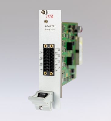
If the IFTA mea­sure­ment sys­tem al­ready of­fers an IFTA AD4IEPE input mod­ule, this can be used with­out using an IFTA GIA-IEPE. Each input of this mea­sure­ment mod­ule has a switch­able IEPE sup­ply and gal­van­ic iso­la­tion al­ready in­te­grat­ed. This also ap­plies to the input mod­ule AD4PS - which of­fers ad­di­tion­al­ly a switch­able volt­age source per chan­nel.

These input mod­ules there­fore offer op­ti­mum sig­nal qual­i­ty and flex­i­bil­i­ty. Both vari­ants are also well suit­ed for mo­bile ap­pli­ca­tions, as ad­di­tion­al elec­tron­ics are elim­i­nat­ed. The am­pli­fi­ca­tion is con­fig­ured via soft­ware and stored along with all of the mea­sur­ing sys­tem's other con­fig­u­ra­tion data. Espe­cial­ly with larg­er test set­ups, this has the de­ci­sive ad­van­tage that changes logged for past con­fig­u­ra­tions can be eas­i­ly re­stored. Thus, sources of error will be avoid­ed and set-up is more flex­i­ble.

IFTA AD4Pro with in­te­grat­ed charge am­pli­fi­er for piezo elec­tric sen­sors

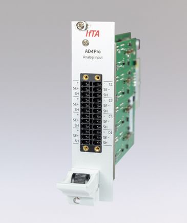
When the dis­tance to the mea­sure­ment sys­tem to be bridged is just a few me­ters, the input mod­ule IFTA AD4Pro can be used. Each input of the mod­ule has its own in­te­grat­ed com­plete charge am­pli­fi­er that can op­tion­al­ly be switched on.

Due to the charge sig­nals short trans­mis­sion paths, this de­sign en­ables op­ti­mal sig­nal qual­i­ty and flex­i­bil­i­ty. IFTA AD4Pro is also suit­able for mo­bile ap­pli­ca­tions, as ad­di­tion­al elec­tron­ics are elim­i­nat­ed. The am­pli­fi­ca­tion is con­fig­ured via soft­ware and stored along with all of the mea­sur­ing sys­tem's other con­fig­u­ra­tion data. Espe­cial­ly with larg­er test set­ups, this has the de­ci­sive ad­van­tage that changes logged for past con­fig­u­ra­tions can be eas­i­ly re­stored. Thus, sources of error will be avoid­ed and set-up is more flex­i­ble.

Rec­om­mend­ed Prod­ucts

Rotor Dy­nam­ics

Ap­pli­ca­tion so­lu­tion to mea­sure/an­a­lyze rotor-dy­nam­ic vi­bra­tions.

Ar­gusOMDS

Pro­tec­tion sys­tem with di­ag­nos­tic and mon­i­tor­ing func­tion­al­i­ty.

Dy­naMaster

Di­ag­nos­tic tool for high-speed anal­y­sis & in­tel­li­gent vi­su­al­iza­tion.

TrendView­er

Fast & in­­­tu­it­ive on­­line/of­f­­line ana­lys­is soft­­ware for ef­­fi­­cient vi­su­al­iz­a­­tion.