

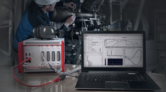
Protection system with diagnostic and monitoring functionality.
Analyzing and Monitoring Shaft Vibrations
As an add-on to IFTA TrendViewer and to our system solutions IFTA DynaMaster and IFTA ArgusOMDS, the IFTA rotor dynamics configuration is the perfect monitoring and diagnostic tool for the protection and the vibration diagnosis of rotating machinery, shaft trains and drive trains. It offers a comprehensive package of individualizable and intuitive software modules within the awarded analysis software IFTA TrendViewer. This allows to identify overloads and machine damage and to react at an early stage to ensure a safe machine operation.
Advantages of the rotor dynamic configuration compared to conventional solutions
Our exclusive rotor dynamic configuration offers significant advantages over the solutions available on the market to date. In addition to a flexible solution, the increase of efficiency and the quality of the measurements, the following benefits are offered:
Adaptive monitoring and Evaluation
- Using user-defined conditions and thresholds in both time and frequency domain, application-specific vibrations can be identified and analyzed. At the same time, the flexibility of the system is maintained.
- Configurable number of tracked harmonics.
- Freely adjustable layouts that make recurrent evaluations easier and significantly faster.
- Offline calculation of additional parameters.
Continuous and thus complete data storage (long-term)!
- Even though there is a considerable amount of data to be stored continuously, we offer a high performance analysis.
- We also offer integrated data storage of vibration data and operating data, e.g. via OPC, Profibus, Modbus, DataSocket, etc.
- Processing of very large data sets (> 10 GB)
Smart data storage management
User-defined conditions and configuration of data storage, such as the conditional storage of startup- and shutdown procedures.
Extensive recording and analysis tools for rotating machines:
- Detect rotational vibrations
- Protection and vibration diagnosis
- Extensive evaluations with the IFTA TrendViewer. evaluation software
Available as software license for IFTA DynaMaster for measurement and analysis and for IFTA ArgusOMDS for protection and analysis.
Active Monitoring of Rotor Dynamics
Rotating machines are monitored in accordance with various standards / requirements (such as DIN ISO 10816, ISO 7919, etc.) The objective of this monitoring is to ensure the safe operation of equipment through the (early) detection of damage to the machine being monitored.
Based on and in addition to these machine protection procedures, a great deal of effort is expended on technical measurement for machinery diagnostics. This begins with the placement of many sensors (shaft- and housing vibration sensors, acceleration sensors, sensors for the measurement of storage temperatures, ...) and ends with the use of special systems for the vibration-diagnostic examination of turbine generators and rotors.
Through these procedures, deviations from normal operating behavior and failure of or damage to components can be detected early, and preventive maintenance measures and general maintenance are easier to plan.
The operational availability of the machine is increased, and the failure of central and important operating components can thus be avoided. With the use of the right measuring technology, complete shutdowns and production losses can be averted - especially in the energy- and process industries.
Rotor Dynamics Phenomena
- Excitation caused by mechanically and thermally induced imbalances on rotating parts
- Excitement caused by rotating parts rubbing on stationary parts
- Parametric excitation caused by rotor sections with different flexural rigidities
- Magnetic force excitation caused by defects and electrical damage to generators, or influences from electrical networks
- Excitation through coupling- and alignment errors
- Bearing instability, an oscillation caused by the properties of the oil film on the bearing
- Vibrational excitation caused by shrink-fit friction
- Wave instability, a vibration caused by aerodynamic forces (excitation gap); caused by unbalanced currents in parts of the flow passage
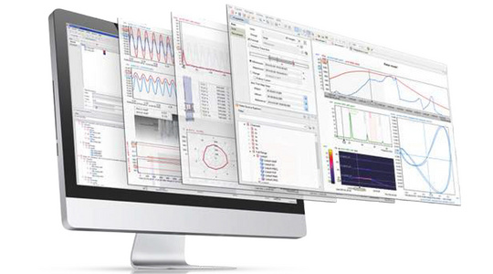
Rotor Dynamics Analysis Software: IFTA TrendViewer
For Powerful Visualizations
With the help of IFTA ArgusOMDS and IFTA DynaMaster systems, it is possible to analyze the machine-dynamic performance of gas turbines, steam turbines, generators or drive trains. The data-analysis software IFTA TrendViewer offer specialized plots that visualize complex facts in a simple manner to analyze rotor-dynamic phenomena fast and extensively.
By combining offline and online data analysis in a single program, vibration parameters from the monitored machine that are currently being measured can be compared with available and shared measurement data. In addition to the dynamic data of the rotor dynamics, slower process variables can also be displayed in the same plot.
Bode Plot
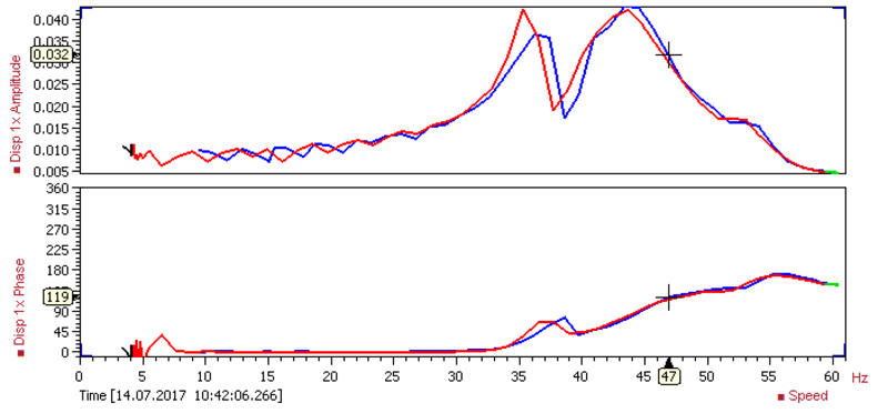
The Bode plot is a popular way to represent transfer functions. The example on the left shows the frequency response of a simple Laval rotor. Readings of the amplitude and phase (relative to a speed signal) of the first harmonic eigenmode can be taken as a function of the frequency (e.g. rotational speed in [RPM]) of the rotor.
Because the IFTA system synchronously samples and analyzes all dynamic channels in real time, a transfer function between any signals can be calculated and visualized "live".
Nyquist Plot
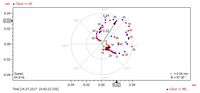
The Nyquist plot shows the imaginary part plotted against the real part of the first harmonic mode of a shaft displacement signal. The point color depends on the machine state (here: black: slow roll, blue: run up, green: steady state, red: run down).
Shaft Centerline Plot
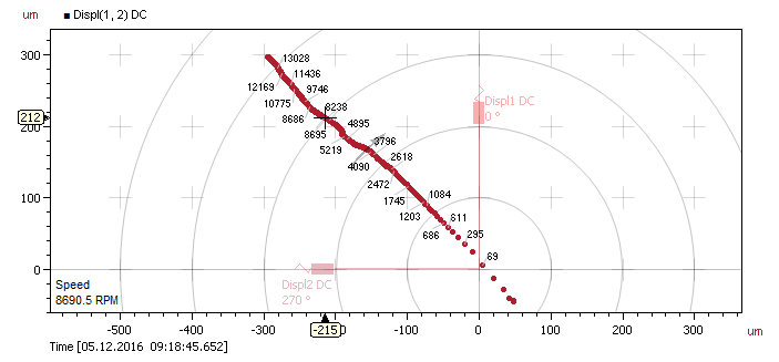
The shaft centerline plot displays the stationary movement of a compressor shaft with respect to a stationary bearing. The mean values of two orthogonal displacement sensors are plotted against each other.
Orbit Plot
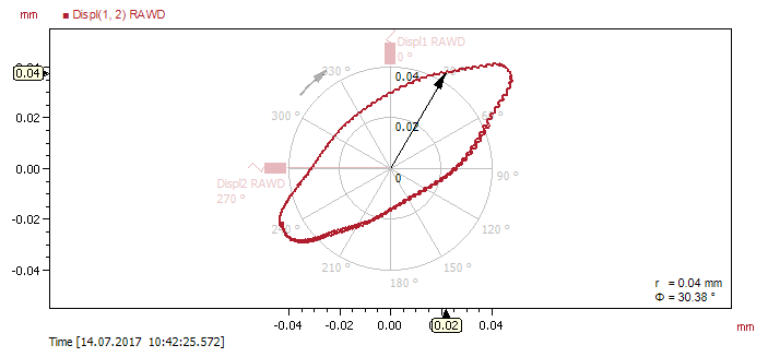
The orbit plot displays the momentary excursion of a rotorkit shaft. Two displacement signals from orthogonal sensors are plotted against each other.
Campbell Plot
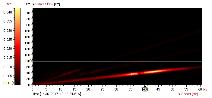
The Campbell plot displays the spectrum of a shaft displacement sensor dependent on a speed signal in a user selected time range. The x-axis displays the speed, the y-axis the frequency and the color bar the magnitude of the spectrum.
Recommended Products
TrendViewer
Fast & intuitive online/offline analysis software for efficient visualization.