Test & Calibrate Measurement Chains
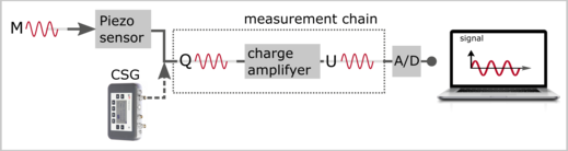
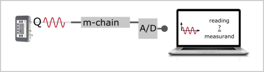
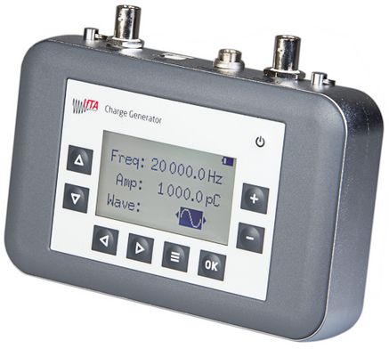
The IFTA ChargeSignalGenerator (CSG) is a charge and signal generator for testing piezoelectric measurement chains. The light and handy device can simulate sensors, e.g. high temperature sensors for pressure and acceleration.
The intuitive operation is carried out via function keys and a 2.7 inch display. Thanks to the battery supply, display back lighting and carrying strap, the charge generator can also be used in places that are dark and difficult to access. For differential charge signals a Lemo connection is available that is identical to the common sensors. Other variants are covered by optional adapters.
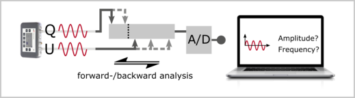
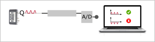
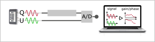
Frequency and amplitude of the output signal are freely determined by the user. In addition to the sinusoidal waveform, the simulator also offers an asymmetric waveform to check the polarity of the cabling of a measurement chain. The synchronous voltage output can also be used to determine transfer functions, e.g. of charge amplifiers.
Through precise digital synthesis, the IFTA ChargeSignalGenerator offers high accuracy and can also be used for calibration. The charge and signal generator can also be ordered factory-calibrated as an option. Calibration is carried out using a device that is traceably calibrated to national standards (DIN EN ISO / IEC 17025).