
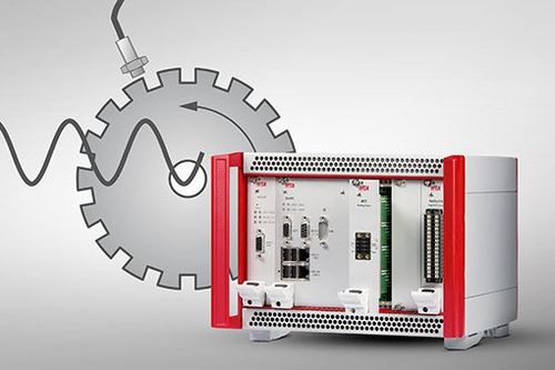
Input module timer AT2 to record torsional vibrations.
Rotational Vibrations - Torsional Analysis
Rotational vibrations in rotating components under alternating torsional loads, such as in gas turbines or in the drive shafts of combustion engines, place high demands on protection and diagnostic systems:
- High sampling rates in the MHz range
- Time-synchronous recording of all measured vibration parameters
- Integration of machine operating data into the measurement data stream
Moreover, torsional vibrations are often not, or only weakly transmitted to the machine housing, especially if the machine has no gearbox. This means that in order to detect torsional vibrations one should not rely on accelerometers/vibration sensors positioned on the housing. Only direct measurement of the torsional vibrations helps to accurately determine the actual component stress.
This is exactly where the IFTA application for rotational and angular vibrations and torsion analyses comes in. We offer a combination of perfectly matched hardware and software components for high-resolution and real-time analyses in an exclusive bundle with our IFTA DynaMaster and IFTA ArgusOMDS system solutions. The torsional vibration data is seamlessly integrated into our ecosystem, directly offering all of our proven functionalities - including protection logic, reliable 24/7 data storage and intuitive visualization.
The core elements of this application are the fiber-optic sensor IFTA LMM2, the High Speed Timer AT2 and the IFTA DSP, which performs the analysis in real-time. Together with the analysis software IFTA TrendViewer, this enables the precise identification of dangerous torsional vibration conditions in order to ensure safe machine operation as well as an increase of the reliability and longevity of your system.
Extensive and high-precision angle-related evaluation of rotational and angular vibrations:
- Identify torsional and angular vibrations
- Combined software and hardware module consisting of the fiber-optic sensor LMM2, the award-winning high speed timer AT2 & the analysis software IFTA TrendViewer
- Flexible design and compatibility with common sensor principles
Available as hard- & software bundle in combination with our system solutions DynaMaster and IFTA ArgusOMDS.
Torsional Vibrations
One speaks of torsional vibrations when a rotating system oscillates about one of its axes. In doing so, a part of the rotational energy usually leads to the periodical twisting - or torsion - of a component in the oscillating system.
Hands-on Knowledge Torsional Vibrations
You are operating a machine where you expect or have even observed torsional vibrations. Initial model calculations or measurements at the machine housing were able to determine the torsional vibrations' characteristic frequencies within an approximate range. Now you want to measure these vibrations and monitor their amplitudes during operation. In the following, we will show you how to proceed efficiently and give answers to the most important questions:
- What does a typical measurement setup look like?
- What should I pay attention to when selecting a sensor?
- How do I choose a suitable rotary encoder for my application?
- Which specification of my measurement system determines the achievable measuring accuracy?
Measurement Setup
Measurement Setup
what belongs where? How are the individual components called?
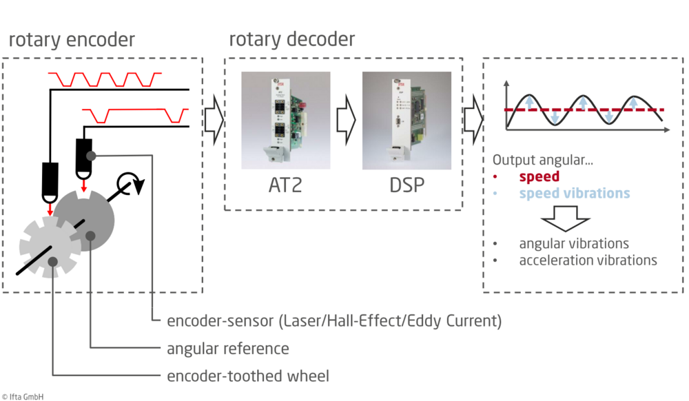
In order to measure torsional vibrations, you essentially need two components, as shown in Figure 1: (1) A rotary encoder and (2) a rotary decoder. The encoder codes the torsional vibration information into a specific output signal, which is decoded by the rotary decoder and converted into the desired output quantity ( rotational speed, angular/speed or acceleration variations). Since such a system evaluates not only the torsional vibration component but also the stationary rotational speed, it is referred to as tachometer.
The rotary encoder usually consists of a gear wheel attached to the shaft to be measured, which is scanned by a distance sensor (the encoder sensor). In doing so, a signal is generated that shows the gear wheel's characteristic contour - consisting of valleys and plateaus. In order to generate an angular reference, often another wheel is used, which has only one tooth or groove and thus defines a zero angle. By means of these two gear wheels, the shaft's current position can then be described uniquely and precisely at any point of time. As an alternative to a gear wheel, depending on the application, so-called zebra tape or a perforated disc is often used. If you are uncertain which method is appropriate for you, we will be happy to assist you.
The signals generated by the rotary encoder are transmitted to the rotary decoder. In IFTA measurement systems, the decoder consists of the timer module IFTA AT2 and a digital signal processor, the IFTA DSP. The AT2 module determines the timing of the valleys/plateaus with high precision and, based on this, the DSP calculates the current shaft speed as well as the angular speed vibrations (or the desired output parameter). A special feature of our systems is that they support an angle reference integrated in the decoder. This eliminates the need for a dedicated gear wheel to define a reference angle: the measurement setup gets simpler and saves space. Instead of an additional gear wheel, the existing one is, for example, provided with one wider tooth or groove. Our decoder can detect this special position and use it as an angle reference.
Sensor Selection
Sensor Selection
Laser, Hall effect or eddy current?
As described above, in the encoder a proximity sensor scans a gear wheel. Depending on the environmental conditions and accuracy requirements, an appropriate sensor must be selected specifically for each application. Laser-based sensors, such as our LMM2 module, offer high focus and precision, but have relatively high requirements on the gear wheel's surface condition. In addition, they can only operate in clean environments that are free of oil, dust and the like. Sensors based on the Hall effect or eddy current principle are less sensitive in this regard. They, however, do not have such a narrow focus. This means that they can detect sharp contours less precisely, but - because of that - are less susceptible to noise. We will again be happy to advise you on this subject if required.
Encoder Selection
Encoder Selection
Maximum resolution of the torsional vibration frequency determines Basic encoder Properties
Let us assume that you have as part of your preliminary analysis determined a maximum expected torsional vibration frequency of 800 Hz. To be on the safe side, you therefore want to select a decoder that can evaluate torsional vibrations up to 1 kHz. Your shaft rotates constantly at 50 Hz. Based on this specification we will show you in the following, how to select a suitable encoder.
Before we proceed with the practical steps, we should first clarify some fundamental concepts. The basic unit of the measuring principle presented here corresponds to a complete rotation of the shaft to be measured. Therefore, all relevant processes are referred to a full shaft rotation . In particular, this means that vibrations are no longer specified in cycles per time (frequency domain) but in cycles per shaft rotation (order domain). As shown in Fig. 2, a vibration mode of order 1 has exactly one cycle per rotation. The same applies to oscillations of higher frequency. In order to convert quantities from the order to the frequency domain, it is therefore necessary to multiply them by the rotational speed.
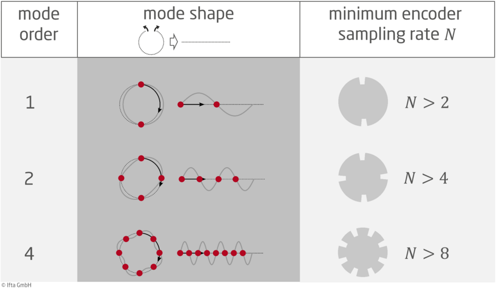
The encoder sampling rate N describes how many measuring points per rotation are recorded by the encoder. In the case of the gear wheel, it corresponds exactly to the number of teeth. It is important to understand that the sampling rate in the order domain ("measuring points per rotation") has a fixed value, namely N. In the time domain, however, the sampling rate ("measuring points per time") scales with the rotational speed, namely rotational speed multiplied by N. High-frequency phenomena can therefore only be investigated at sufficiently high rotational speeds.
Just as in the time domain, the Nyquist-Shannon sampling theorem applies in the order domain, as well: A signal of order O can be reconstructed exactly from a sequence of equidistant samples if it was sampled with an encoder resolution of N > 2 * O. In Fig. 2, right column, this criterion is evaluated for three different mode orders as an example. Since torsional vibrations are not necessarily related to the measurement principle's basic unit, they generally occur at a non-integer order, e.g., 3.42. In such a case, rounding up to the nearest whole number is recommended for determining the minimum encoder resolution, i.e., 4 in this case.
Equipped with this knowledge, the encoder requirements for the aforementioned example can be calculated as follows:
- A vibration of 1 kHz at a speed of 50 Hz corresponds exactly to a mode of order O = 1000/50 = 20.
- As a result, according to Nyquist-Shannon, an encoder with a resolution of N > 2 * 20 = 40 is required.
- In practice, it has been proven to add approx. 25 % to this number. Accordingly, an encoder with at least N = 50 teeth/slots should be selected.
Measuring Accuracy
Measuring Accuracy
Accuracy is determined by sampling rate - not bit depth
A variety of factors influence the accuracy during a measurement, for example, the signal-to-noise ratio or the selection and mounting of the encoder. In the following, however, we will deal specifically with the influence of the digitization of the analog sensor signal.
By definition, the resolution of a measurement corresponds to the smallest change that can be detected in the parameter being measured. For voltage measurements, the resolution is determined by the bit depth of the analog-to-digital converter. An 8-bit converter can encode 256 different voltage values, while a 12-bit converter can encode 4096. This means that the 12-bit converter has a higher resolution than the 8-bit converter, because the former can detect smaller changes in the voltage signal. As a result, the measuring accuracy increases with the bit depth of the converter - at least if other factors are neglected.
However, in the context of torsional vibration measurements, it is not the amplitude information of a voltage signal that is to be digitized, but the exact times at which the signal amplitude falls below or exceeds a previously defined threshold value (trigger event). This is illustrated in Fig. 3: Whenever the analog input signal crosses the threshold value, the digital output signal changes its state from "high" to "low" or vice versa. Based on the digital signal generated in this process, the point of time of these trigger events can subsequently be determined with an accuracy of Δt. The value of Δt is derived from the sampling frequency. Our IFTA AT2 timer module samples at a frequency of 100 MHz, allowing trigger events to be detected with an accuracy of 10 ns.
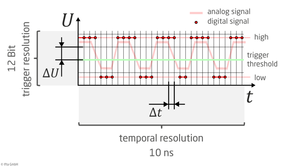
The trigger resolution defines which voltage values can be set for the trigger threshold. Our IFTA AT2 timer module offers 12 bits here, i.e. 4096 possibilities in the range from -25 V to +25 V. It is important to understand that this value does not say anything significant about the accuracy of a torsional vibration measurement. The time resolution described above is the relevant factor here.
Advantages of the IFTA Application for Torsional Measurement
High precision
The core module of this application, the IFTA High Speed Timer AT2, provides a temporal resolution of 10ns. This corresponds to a frequency of 100 MHz and allows us to identify and analyze difficult to detect vibrations such as rotational, angular and torsional vibrations.
Reliable protection
In combination with the IFTA DynaMaster or IFTA ArgusOMDS, e.g. long-term recording, triggered data storage with pre- and post-trigger as well as protection shutdowns are possible.
Flexibility & Compatibility
Facilitated and flexible design and compatibility with common sensor principles. High input impedance (e.g. photodiodes can be connected directly). Easily and quickly adjustable trigger threshold enables automatic tracking under changed measurement conditions.
Save costs
Analog signals, e.g. from common distance sensors, can be fed in directly and can be resolved in the picosecond range via threshold value-defined triggers, i.e. there is no need for external processing electronics for analog incoming signals. This results in cost savings and higher signal quality.
The Application's core, the High Speed Timer AT2
The outstanding precision and versatility of the input module resulted in the award of the messtec + sensor masters (2nd place) in 2017.
Analysis of Rotational Vibrations - Usability Example
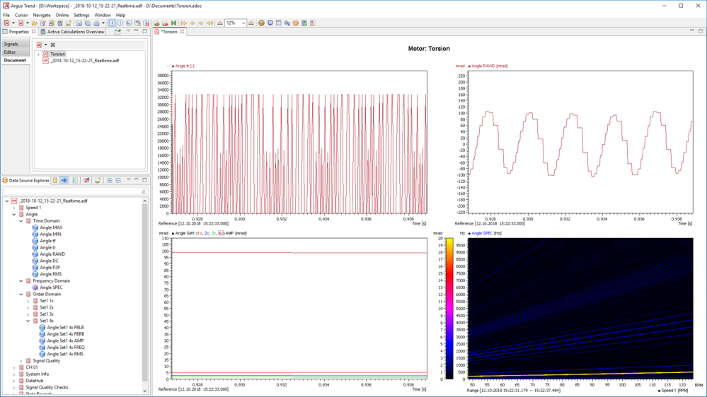
At first, the High Speed Timer AT2 measures impulses with high temporal resolution (top left in the figure).
Depending on the specific configuration, this raw data can be used to calculate signals for speed, vibration angle, vibration speed or vibration acceleration, for example. Like any other input signal, these can be used for further analyses, e.g. FFT. For subsequent analysis purposes, these quantities are correlated in characteristic plots.
In the example we have chosen, the high-resolution raw data (top left) is used to calculate the vibration angle (top right). From this, for example, harmonics can be determined, in this case with a strong amplitude of the 4th order (bottom left). A Campbell plot also illustrates the results of the frequency analysis (bottom right: spectrum plotted over the rotational speed).
Recommended Products

TrendViewer
Fast & intuitive online/offline analysis software for efficient visualization.