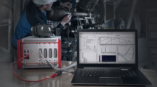

Application solution to measure/analyze rotor-dynamic vibrations.
Highlights
- Galvanic isolation between input and output side and to the supply region
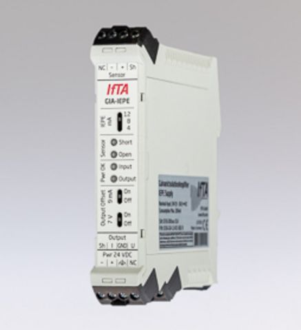
- Adjustable IEPE supply
- Voltage and current output
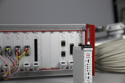
- Integrated detection of whether the input is short-circuited or open: Signals errors at the voltage and current output, if necessary, as well as optically via status LEDs
- An additional DC offset can be activated at the voltage and current output to communicate to the measurement system that the measurement chain is in operation.
- Excellent EMC characteristics
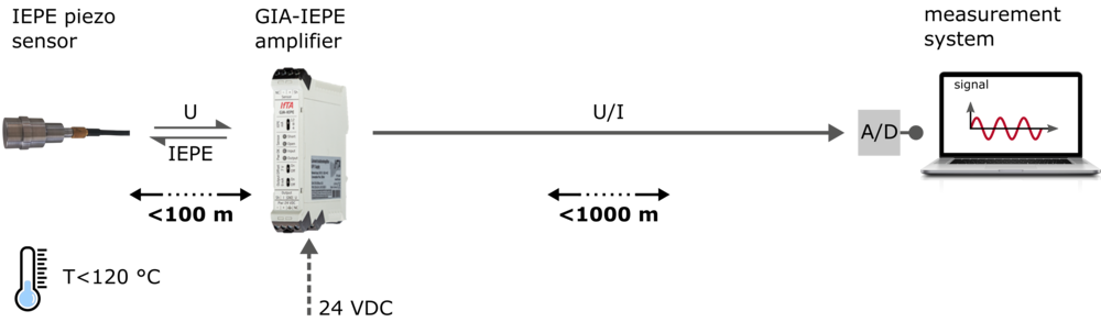
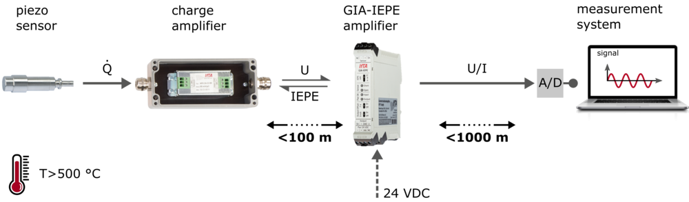
- Suitable for long cable lengths of up to several hundred meters
- Ideal for use with IEPE sensors and IEPE charge amplifiers
- Compatible with standard measurement technology