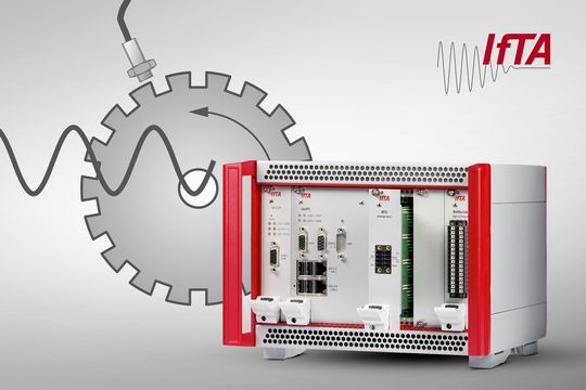
Stationary Installations
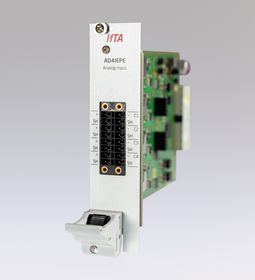
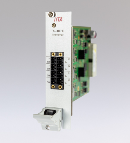
The AD4IEPE is primarily used in stationary installed industrial machinery. Measurement signals from external pre-amplifiers or signal converters can be connected to the AD4IEPE either as voltage signals or as current signals. Likewise, common industrial standard signals can be applied directly by a control system (±10 V, 0-10 V, 4-20 mA, etc.). In addition the module offers a switchable IEPE supply on each channel.
Especially when there are large distances between the control room and the measuring site, galvanic isolation is required - not only for the desired signal, but also for the voltage supply of the sensor or charge amplifier. IEPE technology incorporates both into a single 2-wire cable. Especially in applications with large numbers of measuring locations, IEPE enormously simplifies the installation effort and measurement setup.
This standard is applied to sensors such as acceleration, force and pressure sensors or microphones and differs in its designation depending on the manufacturer. ICP© (integrated circuit piezoelectric), CCLD© (constant-current line-drive), IsoTron©, DeltaTron© or Piezotron© are some examples.
Service
Thanks to the flexible push-in connectors, installation cables can be laid directly or with wire end sleeves, without the need for time-consuming connector assembly.
Test benches
The AD4IEPE is also recommended for test benches, since galvanic isolation of the power supply from pre-amplifiers or sensors is also advantageous for them: With 2-wire cables, the wiring effort per measuring site is extremely low, making wiring easy to manage and therefore less prone to errors.