Temperature measurement by thermo elements or resistance thermometers.
Temperature Measurement for Condition Monitoring

The analysis of machine vibrations usually requires the recording of slowly changing state variables (or operational data), additionally to the vibration data. Only in combination, these different types of measurement data provide a comprehensive picture of the current overall machine condition. Temperature is an important example of such a state variable, essentially for three reasons:
Detection of damage and unfavorable operating Points
Mechanical friction and pressure lead to the conversion of mechanical energy into heat, e.g., in bearings, gears or hydraulic systems. This is especially true in the case of faulty or damaged machine components: They often lead to a locally increased heat input and thus a measurable rise in temperature. Hence, continuous temperature monitoring can help to detect problems and prevent damage. Furthermore, lubricating and hydraulic oils should not leave an optimum temperature range in order to maintain their favourable characteristics. The continuous measurement of the oil temperature can detect a deviation from the permissible range and countermeasures for cooling/heating can be initiated.
Conversion of chemical energy requires good thermal management
In many machines, chemical energy is converted into mechanical or electrical energy, e.g. in combustion engines, gas turbines or electric cars (there in the batteries or fuel cells). In all cases, heat is generated that has to be removed for the continuous operation of the machine. This requires well planned thermal management, which can be effectively validated and monitored by temperature measurements.
Electrical machines also experience significant heat input
The same applies to electrical components, such as electric motors or generators, except that the reason for the heat input here - in addition to mechanical friction - are current flow or magnetic hysteresis losses of components.
Thermometer Errors
Challenges in temperature Measurements
The most common measurement principle for determining temperatures is based on bringing a sensing element into thermal contact with the measured object. In doing so, the sensing element adapts to the temperature of the measured object and generates an electrical measurement variable from which we can conclude the temperature of the sensing element - and thus of the measured object. Basically, two types of errors always occur, which are of varying importance depending on the application and the measuring device used:
Type I Error
Since the sensing element adopts the temperature of the measured object only after a certain period of time, the measured temperature always lags somewhat behind the temperature to be measured. This time lag, characterized by a time constant, becomes shorter the lower the transducer's heat capacity and the better the thermal contact with the measured object is.
Type II Error
If the transducer is not exclusively in thermal contact with the measured object, it can adopt a temperature that differs from the one of the measured object. For example, in high-temperature applications heat transfer by radiation plays an important role. When determining the hot gas temperature in a combustion chamber, it can happen that the transducer is not only in thermal contact with the gas, but also - via radiation - with the cooler combustion chamber walls. As a result, the temperature measured is systematically too low. This effect can be mitigate, for example, by mirroring the probe or by attaching a radiation shield.
The Selection of Sensors
In industry, one encounters mainly three types of electrical temperature measurement sensors: resistance thermometers, thermistors and thermocouples. All of them have individual advantages and disadvantages and are therefore suitable for different applications.
Resistance Thermometers or Resistance Temperature Detectors (abbrev. RTD)
Widerstandsthermometer/Resistance Temperature Detector - RTD
Dieser Sensortyp nutzt aus, dass der Widerstand metallischer Leiter temperaturabhängig ist. Die Temperaturmessung wird somit auf eine Widerstandsmessung zurückgeführt. Ein Metall-Leiter, der für eine Referenztemperatur einen definierten Widerstand aufweist dient hierbei als Messaufnehmer. Weit verbreitet ist hierbei das sogenannte Pt-100 Widerstandsthermometer, welches einen Aufnehmer aus Platin (chem. Pt) besitzt, der bei 0°C einen Widerstand von 100 Ohm besitzt. Aufgrund der relativ geringen Aufnehmerwiderstände von RTDs, können die Widerstände der Leitungen, mit denen der Messaufnehmer an das Messgerät angeschlossen wird, einen signifikanten Einfluss auf den Messwert haben. Zur Kompensation dieses Einflusses, wird häufig anstatt der einfachen 2-Draht Messung die etwas aufwändigere 3- oder 4-Draht Methode angewandt.
Vorteile der Widerstandsthermometer:
- Langzeitstabil
- Recht großer Messbereich
- Lineares Temperaturverhalten
- Relativ genau (auch bei hohen Temperaturen)
- Robust gegen elektromagnetische Störungen
- Lange Lebensdauer
Nachteile der Widerstandsthermometer:
- Teuer
- Langsame Ansprechzeiten/große Zeitkonstante
- Relativ große Bauform
- Geringer Aufnehmerwiderstand wodurch lange Anschlusskabel das Messergebnis verfälschen
Typische Anwendungen:
- Präzise Messungen bei hohen Temperaturen (Prozessüberwachung und -steuerung)
- Messungen unter signifikanten elektromagnetischen Einflüssen (Generatoren, Hochspannungsanlagen)
Thermistors NTC and PTC
Thermistors: NTC and PTC
Like RTDs, this type of sensor is based on resistance measurement to determine temperature. Contrary to RTDs, however, thermistors are based on semiconductor metals. A distinction is made between (1) PTC - Positive Temperature Coefficient - thermistors, whose resistance increases with temperature, and (2) NTC - Negative Temperature Coefficient - thermistors, whose resistance decreases with temperature. Due to their higher resistance and their significantly larger dynamic range, mainly NTC thermistors are used for temperature measurement. Silicon-based linear PTC thermistors are an exception, but they are relatively new and therefore not yet very common.
Advantages:
- High precision
- Short response times/small time constant
- High resistance which allows the use of longer cables
- Resistant to shock and vibration
- Favorable price
Disadvantages:
- Only for low temperatures with small temperature ranges
- Strongly non-linear temperature behavior
Typical applications:
- Economical and precise temperature measurement at low temperatures (<130°C)
- Large quantities possible at small required space (household appliances, medical technology, automation)
Thermocouples
Thermocouples
This type of sensor consists of two metallic conductors of different material, which are connected to each other at the measurement point. At a reference junction, a voltage can then be measured between the two conductors, which is proportional to the temperature difference between the measurement point and the reference junction. Knowing the reference junction temperature, the absolute temperature at the measurement point can be determined from this differential temperature. The required reference junction temperature is usually measured with the aid of an RTD. Depending on the material combinations, sensitivities and measuring ranges of the respective thermocouples vary. The most important combinations are standardized according to DIN EN 60584-1 and are marked with a capital letter, e.g. "K" for chromel (NiCr) and nickel (Ni) or "J" for iron (Fe) and cupronickel (CuNi). Moreover, for easy identification of the thermocouple type, connecting cables have different color codes.
Advantages:
- Cover a large temperature range
- Suitable for very high temperatures
- Short response times/small time constant
- Resistant to shock and vibration
- Favorable price
Disadvantages:
- Comparatively inaccurate
- Signal quality decreases over time
- Prone to electromagnetic noise due to small measurement signals
- Complex signal processing necessary
- Requires cold junction compensation
Typical applications:
- Measurement of very large temperature ranges at high temperatures
- Functional even under harsh conditions (annealing and firing furnaces, process monitoring)
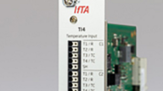
Measurement System with Integrated Temperature Input Module
No matter which choice you take - one solution for all cases
The IFTA temperature measurement module TI4 offers a carefree package for temperature measurement: To each of Its 4 electrically isolated inputs RTDs, thermistors or all common thermocouples can be flexibly connected. It supports all common measurement principles, for example: 2-, 3- and 4-wire measurement for RTDs, high-precision cold junction compensation using Pt-100 resistance thermometers as well as support for differential measurements for thermocouples, or accurate processing of non-linear behavior for thermistors. In our familiar graphical user interface all measurement settings can be adjusted conveniently and saved in configuration files for later use or exchange with colleagues.
Recommended Products

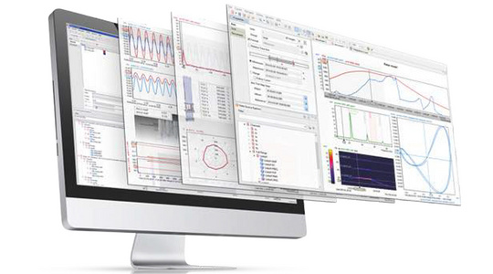
TrendViewer
Fast & intuitive online/offline analysis software for efficient visualization.